June 17, 2026 tasmota esp8266 esp8285 sinilink home-automation picocom
TL;DR:
I flashed Tasmota 15.4 onto Sinilink XY-WFUSB modules (ESP8285) using a 6-pin UART header, fixed a classic TX/RX swap mistake, then automated GPIO/template setup with small shell scripts because the web UI was painfully slow and the Blakadder template alone did not expose the relay toggle.
Later I also burned hours thinking serial TX was dead (boot logs OK, typed Status 2 silent) even though UART flash worked. Cause: minicom sends CR on Enter; Tasmota’s serial console only completes a command on LF. Use picocom with --omap crcrlf (and local echo) instead.
All scripts and notes: stulluk/xy-wfusb
Introduction
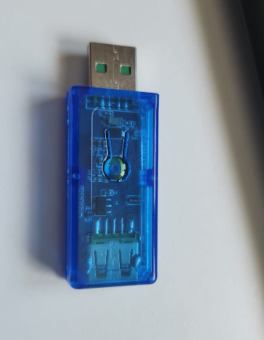
The Sinilink XY-WFUSB is a compact Wi-Fi USB power switch — essentially a relay behind a USB socket, with a button and a few status LEDs. Inside is an ESP8285 (ESP8266-class core with embedded flash).
I already run several Neo/Tuya wall plugs on Tasmota 9.2.x (programmed years ago with tuya-convert). This Sinilink board is different: it exposes a programming header, so there is no OTA trick — you wire 3V3, GND, IO0, TX, RX and use esptool.
Goal: local ON/OFF via button, web UI, and curl, without Tuya cloud — same spirit as the Neo plugs, but over UART.
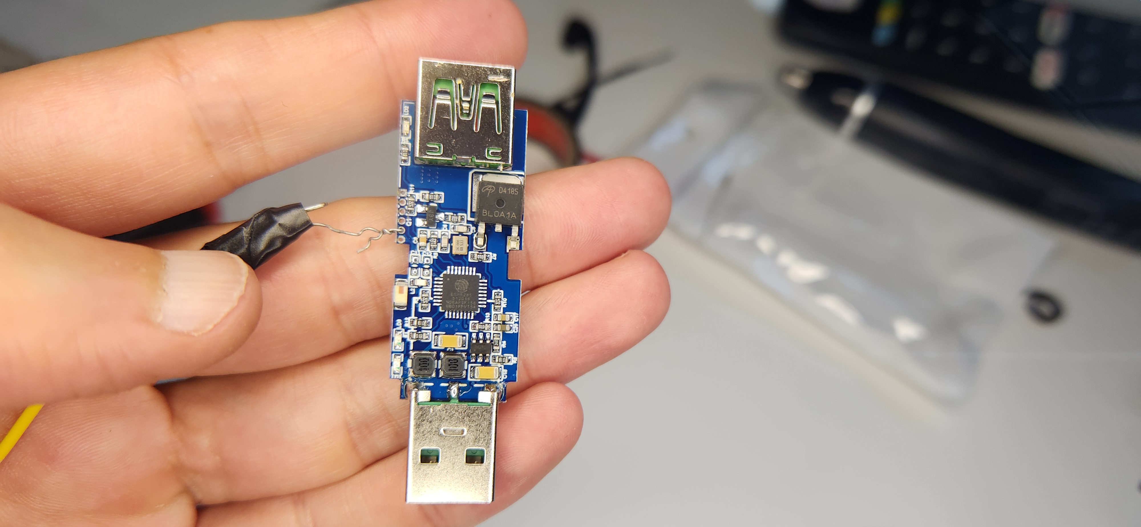
Hardware: 6-pin header (RST not used)
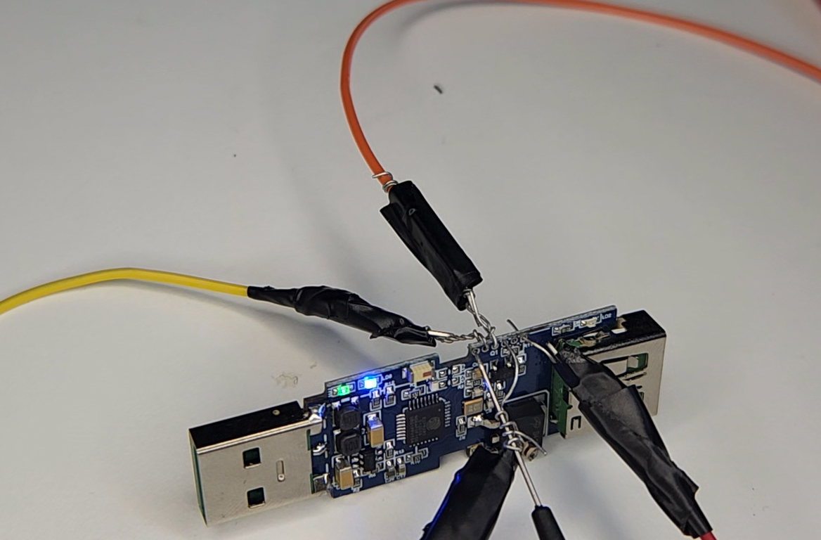
On the board there is a 6-pin programming header. I connected everything except RST:
| Pin | What I did |
|---|---|
| 3V3 | Module power — 3.3 V only |
| GND | Common ground with USB-UART |
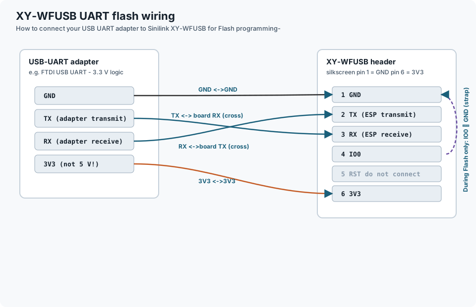
| IO0 | Strapped to GND during flash (download mode) |
| TX / RX | Crossed with the adapter: adapter TX → board RX, adapter RX → board TX |
| RST | Left floating (not wired in my setup) |
Important: IO0-to-GND alone is not enough — you still need 3.3 V on VCC. Without power, esptool will sit there forever with No serial data received.
Flash programming wiring diagram
Correct USB-UART ↔ header map (TX/RX crossed, pin 6 is 3V3 not 5 V, RST unused, IO0↔GND only while flashing):
Problem-1: esptool cannot connect
First flash attempt failed. esptool sent sync bytes; nothing came back on RX.
Cause: TX and RX were not crossed — a mistake I have made more than once on ESP boards.
After swapping TX/RX, the same command worked immediately. esptool reported:
- Chip: ESP8285N08
- Flash: embedded, 1 MB
- Parameters that worked:
dout,40m
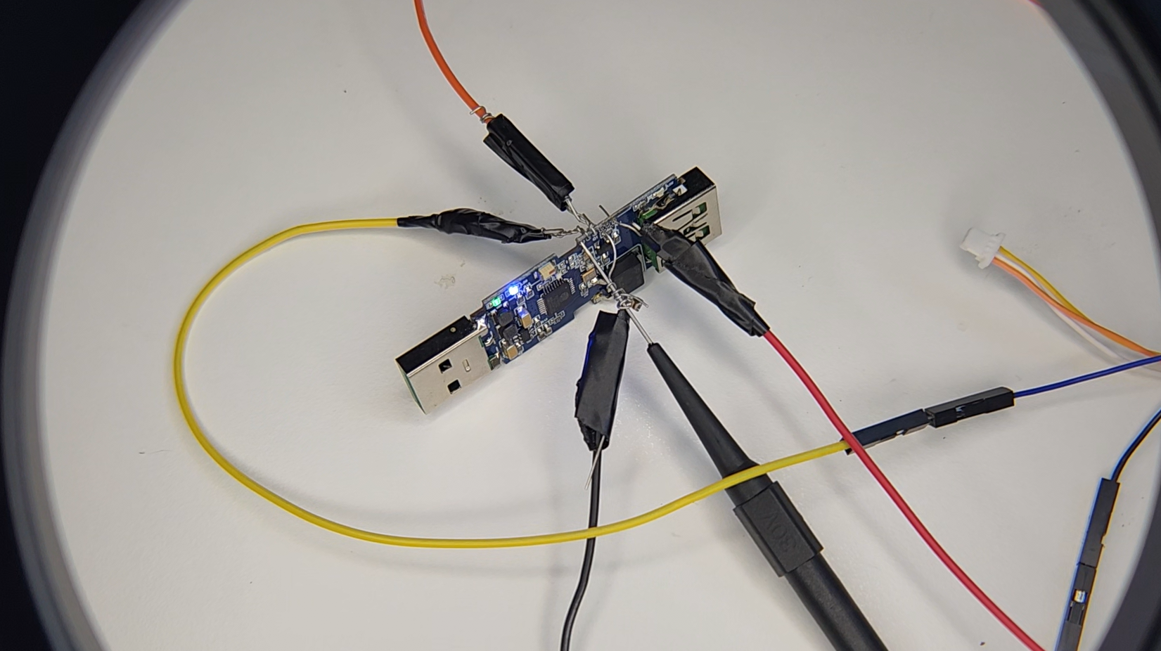
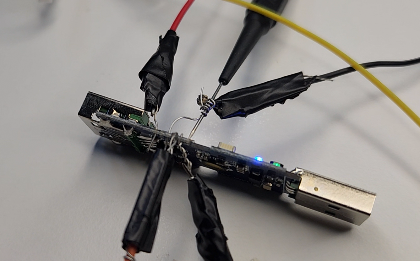
Solution to Problem-1: scripts in the repo
I put the repeatable flow under flash/ in stulluk/xy-wfusb:
cd flash
./setup_env.sh          # local venv + esptool (no system packages)
./download_tasmota.sh   # official release tasmota.bin
./flash_xy_wfusb.sh /dev/serial-ws6   # your tty may differ
After flash: remove IO0–GND strap, power-cycle, join Wi-Fi from the Tasmota AP portal.
Problem-1b: “Serial TX is broken” (minicom) — but esptool just worked
Months later, flashing another unit (custom v1.5 image), I hit a very confusing combo:
- Power-cycle → Tasmota boot log streamed fine at 115200 (board → PC OK).
- UART flash with esptool succeeded again (PC → board OK in download mode).
- In minicom, typing
Status 2+ Enter did nothing — noCMD:, noRESULT. Hardware and software flow control were both Off. Continuity on adapter TX → board RX looked fine.
That looks exactly like “PC cannot talk to the ESP” — except flash had already proved the wire.
Cause: CR vs LF (not a broken TX pin)
Tasmota’s serial console (SerialInput in the firmware) only treats a line as complete when it sees \n (LF). Characters are buffered; \r (CR) alone does not run the command.
minicom (classic terminal behaviour) usually sends only CR when you press Enter. You still see what you typed (local echo / timestamped lines), so it feels like the board “ignored” you. Leftover buffer junk can also produce weird CMD: ss 2Status 2 / Unknown once an LF finally arrives (e.g. Ctrl+J).
This is not a security feature — just Unix/Arduino line-ending habit vs old serial-terminal Enter.
| Tool | Enter typically sends | Tasmota console |
|---|---|---|
| minicom | CR (\r) | Silent (command not executed) |
| Ctrl+J in minicom | LF (\n) | Works |
picocom --omap crcrlf | CR+LF | Works (LF completes the line) |
| esptool | binary protocol | Unaffected |
Solution: picocom with CR→CRLF mapping + local echo
picocom -b 115200 --omap crcrlf --echo /dev/serial-ws7
(Use your FTDI symlink; mine was /dev/serial-ws7 for that session.)
--omap crcrlf— map outgoing CR to CR+LF so normal Enter works with Tasmota.--echo(or--echo yes) — local echo so you see what you type.- Exit: Ctrl-A then Ctrl-X.
Sanity check after boot (IO0 strap removed):
Status 2
You should see CMD: Status 2 and a STATUS2 = {...} JSON line. From there, serial Backlog for SSId1 / Password1 / FriendlyName1 works the same way.
minicom note: “Add linefeed” under Screen and keyboard affects received display, not what Enter transmits — so it does not fix this.
Problem-2: web UI almost unusable
Unit #1 joined my home SSID (STEW-24) and got DHCP (192.168.1.169 in that session).
- Ping worked (sometimes jittery latency).
- The main HTML page often timed out or took tens of seconds.
- The lightweight
/cm?cmnd=...JSON API was still reachable.
So I stopped relying on the browser for configuration and used curl and small shell scripts instead. This is normal on ESP8266-class hardware with the full Tasmota web UI — not a “wrong firmware version” issue.
Problem-3: Blakadder template “applied” but no ON/OFF button
Blakadder’s XY-WFUSB template is the right GPIO map. I pasted the JSON via Template { ... } and set Module 18 (Generic).
What went wrong:
- Reading back
Templateshowed correct JSON. Gpiostill looked like all None.Power1/Statehad no POWER field — the main web page showed Generic with no toggle.
The template was stored, but the runtime GPIO map did not land until I assigned pins explicitly:
GPIO4→ Button1 (32)GPIO5→ Relay1 (224)GPIO14→ green LED — see LED section belowGPIO16→ LedLink (544)
Solution to Problem-3: apply_xy_wfusb_tasmota_api.sh
After the device has a LAN IP:
cd flash
./apply_xy_wfusb_tasmota_api.sh 192.168.1.169
The script pushes Module 18, the template JSON, explicit GPIO roles, and Restart, then prints Template, Module, Gpio, and Power1 for a quick sanity check.
Remote control (works even when the web UI is slow):
curl -sS "http://192.168.1.169/cm?cmnd=Power1%20On"
curl -sS "http://192.168.1.169/cm?cmnd=Power1%20Off"
curl -sS "http://192.168.1.169/cm?cmnd=Power1%20Toggle"
LED behaviour (blue vs green)
During script testing the LEDs did strange things — several reboots and Power toggles will do that.
After things settled:
| LED | Behaviour |
|---|---|
| Blue (LedLink, GPIO16) | Blinks while Wi-Fi is connecting; off when associated |
| Green (GPIO14) | Stock Blakadder uses inverted Led_i1 → green on when relay OFF |
I preferred green on when output is ON. That is Led1 (288) on GPIO14 instead of Led_i1 (320). The apply script uses 288 in both the live GPIO command and the stored template.
There is also a red LED tied to the relay hardware; it is not configurable in Tasmota the same way.
Friendly names for multiple units
Second board: same flash flow, new DHCP IP (192.168.1.176), label XY-WFUSB2:
./apply_xy_wfusb_tasmota_api.sh 192.168.1.176
./xy-wfusb-set-friendly-name.sh 192.168.1.176 XY-WFUSB2
Renaming is cosmetic — it does not break relay logic or MQTT Topic (still derived from MAC, e.g. tasmota_64661D).
Tasmota 9.2 vs 15.4 — wrong rabbit hole
My older Neo plugs still show Tasmota 9.2.0. These Sinilink units run 15.4.0 on ESP8285.
That is not an incompatibility. 15.4 is appropriate for this chip. Downgrading to 9.x would be a step backward without fixing the slow web UI or the template/GPIO quirk.
Lab record (two units)
| Unit | MAC (esptool) | DHCP IP (example) | Friendly name |
|---|---|---|---|
| 1 | C8:2B:96:64:64:FC | 192.168.1.169 | XY-WFUSB1 |
| 2 | C8:2B:96:64:66:1D | 192.168.1.176 | XY-WFUSB2 |
End-to-end flow
Wire header (RST optional) → IO0 strap → 3V3 + GND → flash tasmota.bin (or custom v1.x)
    → if sync fails: swap TX/RX
    → remove IO0 strap → Wi-Fi portal (or serial Backlog via picocom)
    → optional: apply_xy_wfusb_tasmota_api.sh <IP> (stock FW only; custom v1.4+ usually not needed)
    → xy-wfusb-set-friendly-name.sh <IP> <LABEL>
    → verify button + curl Power1
Serial console tip: prefer picocom -b 115200 --omap crcrlf --echo over plain minicom Enter.
References
- Blakadder — Sinilink XY-WFUSB
- Tasmota esptool docs
- picocom (
--omap crcrlf) - GitHub — stulluk/xy-wfusb (scripts + README)
- My earlier Neo / tuya-convert write-up: Wifi Programming Neo PowerPlugs with tasmota firmware